

The objective of this project was to design a new type of mesofluidic diode (i.e., passive check valve) – one that was comprised of at least two distinct materials, to take advantage of the multi-material printing capabilities of the Objet500 Connex3 Polyjet 3D Printer. The printing materials included a flexible, rubber-like material,TangoBlack FLX97, and a more rigid, plastic-like material,VeroClear RGD81. The goal of the design challenge was to invent a mesofluidic diode that exhibited the largest diodicity – the ratio of ‘allowed’ to ‘obstructed’ fluid flow. And in doing so, exercise the additive design knowledge, learned throughout the course, by maneuvering through the manufacturing obstacles associated with this particular printing process.
Design Challenge
Background

Design Process
Umbrella Diode
My inspiration for the umbrella diode design comes from a small valve manufacturing company, Minivalve. Minivalve, founded in 1999 by Peter Nijland, develops and distributes miniature self actuating valves, predominantly one way valves, like the umbrella. The umbrella concept allows for the material properties and geometry, particularly the thickness, of the umbrella component to dictate the working pressure of the diode. In forward flow conditions, the umbrella’s diaphragm like flap acts as a spring sealing the inlet flow until a minimum pressure is reached. When reached, the umbrella is forced into a convex shape, allowing water to pass. In backflow conditions the umbrella’s flap is encouraged by the flow to reseal the previous inlet, preventing any flow movement.
The design of the female inlet/outlet ports were provided by Ryan Sochol, the course instructor, and integrated into each students housing, so that the designs would be compatible with the tubing used in testing procedures. The remainder of the housing, and umbrella component, were both designed in Solidworks by myself and Vineet Padia.
All designs were submitted, in two self-referenced STL files corresponding to the two materials, to Terrapin Works to be printed.

Test Results
Umbrella Diode
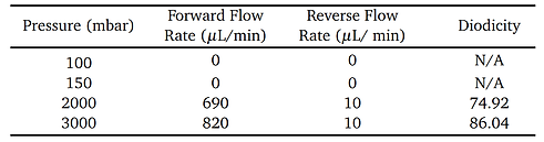
The umbrella valve was one of three designs that we considered successful in realizing design objectives for the project. Initially displaying infinite resistance for both forward and back flow conditions, the design eventually became fully functional at higher pressures. Its large cavity size, in relation to the size of the inlet and outlet cross section, contributed to the lack of support removal and its initial dysfunction. Experimentally, it performed as expected only at higher pressures. The table, to the left, is a synopsis of the performance of the three diodes that had the most support material removed to allow functionality. They display an average diodicity of approximately 80, meaning successful additional impedance in backflow conditions compared to forward flow. The plot, to the left, displays the diodicity vs. reynolds number for the three successful diodes.

Testing Procedure
After being processed for several days, the prints were inspected before testing. It was found that the majority of the prints had either the support material only partially removed or structural failures. The umbrella diodes were of the former, so the manual removal of support material was necessary before testing. After the brief cleaning, each umbrella diode was attached to a Fluigent flow rate platform, in either the forward or back flow configuration. This apparatus allowed us to monitor the flowrate of attached diodes as we varied the pressure. Each diode's inletport was attached to a clear inlet tube leading to the Fluigent apparatus and water reservoir. Another length of clear tubing was connected from the outputport to a small beaker to collect the output fluid. While incrementally increasing the pressure the flowrate was recorded, manually, and displayed using the Fluigent software. This process was then repeated switching the flows direction by reversing the orientation of the diode.


Conclusion
Umbrella Diode
The multi-material aspect of polyjet based design contributed to the success of actuating diodes. This variance in material allowed for design flexibility centered around the material’s properties. These properties combined with tolerancing, specifically in the umbrella diode, were key to its’ performance. A balance must be reached between the designed thickness of the rubber component and the post processing involved with polyjet 3D printing. If this part is designed too thin you risk damaging the rubber via erosion during soluble support removal. If designed too thick you increase the minimum working pressure for the diode. For the umbrella diode, I designed too thick. As seen in the experimental results, the working pressure is ten time that of other diode designs.
A relationship between the successful removal of support material and relative size of the inlet/outlet cross section to diode cross section was found during experimentation. The Tesla Flap, Sochol, and plunger diodes, seen on the left, had support removed successfully, while the umbrella, perforated, and plunger valves remained filled with support. The distinction between the three suggest that the ratio of the inlet and outlet cross section to the diode cross section must be less than or equal to one, or close to one. Ratios that are too large increase the volume of support material within the diode, while maintaining the same access constraint, the inlet/outlet cross section. More research must be done to establish an explicit relationship between the inlet/outlet cross section to the inner feature cross section of MJM printed devices; and the effects these parameters have on the rate of mass transfer during support removal. It is also worth noting that our designs shared the solvent solution with another group of parts that had an excessive amount of support material in and around the diodes. This diluted the chemical mix and undoubtedly made the removal process move slower.


Phone
240-750-3186

PROJECTS
THE PAST AND FUTURE PROJECTS OF MARCUS MARTIN

IMAGE BY
VINEET PADIA

